Most electrical fires and equipment failures do not happen without warning. They almost always start small, as a loose terminal, a corroded connector, or an overloaded circuit that quietly heats up long before anyone notices smoke or sparks. The problem is that this early heat buildup is invisible to the naked eye and hidden inside panels, switchgear, and cable runs where nobody thinks to look. This is exactly the kind of hidden danger that an electrical thermography test is built to catch.
Across Pakistan, from textile mills in Faisalabad to shopping malls in Lahore, hospitals in Islamabad, and factories in Karachi, electrical systems run harder and longer than they were often designed for. Voltage fluctuations, frequent load shedding and restoration cycles, and dust-heavy environments all put extra stress on wiring, breakers, and connections. Over time, this stress creates weak points that generate excess heat. Electrical thermography testing uses infrared imaging to find those weak points before they turn into breakdowns, fires, or costly downtime.
In this guide, we explain exactly how electrical thermography tests work, what kinds of hidden faults they detect, why heat is such a reliable early warning sign, and how facilities across Pakistan can use regular thermal inspections to protect people, equipment, and property.
What Is an Electrical Thermography Test?
Fire Safety Trading (Pvt)
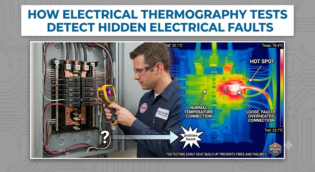
ToggleAn electrical thermography test is a non-contact diagnostic inspection that uses an infrared (thermal imaging) camera to measure the surface temperature of electrical components while the system is running under normal load. Because faulty connections and overloaded components generate more resistance, and resistance generates heat, a thermal camera can spot a developing problem simply by showing where a component is hotter than it should be compared to similar components around it.
Unlike many other electrical tests, thermography does not require the system to be shut down or de-energized. The equipment is inspected live, while it is doing real work, which is exactly when hidden faults reveal themselves through heat. This makes thermography one of the few electrical diagnostic methods that can be carried out without interrupting production, business operations, or essential services.
Why Heat Is the Earliest Sign of an Electrical Fault
Electricity flowing through a properly connected, correctly sized conductor produces very little heat. The moment resistance increases anywhere in the circuit, whether from a loose screw terminal, a corroded lug, an undersized cable, or an unbalanced load, the same amount of current has to push through a tighter bottleneck. That bottleneck converts electrical energy into heat at the point of resistance.
This heat builds up gradually, often for weeks or months, long before there is any visible sign such as discolouration, a burning smell, or a tripped breaker. A thermal camera picks up this temperature rise at a stage when a simple tightening, cleaning, or component replacement is enough to fix it. Waiting for a visible or audible warning sign usually means the fault has already progressed to the point where a shutdown, an equipment failure, or a fire risk is close behind.
How Electrical Thermography Tests Actually Detect Hidden Faults
1. Infrared Radiation Measurement
Every object above absolute zero emits infrared radiation, and the intensity of that radiation increases with temperature. A thermal imaging camera contains a sensor that detects this infrared radiation and converts it into a visual image called a thermogram, where different colours represent different temperatures. Technicians usually use a colour scale where white, red, and orange represent hotter areas, while blue, purple, and black represent cooler areas.
2. Comparative Analysis Between Similar Components
A single temperature reading rarely tells the full story on its own. Trained thermographers compare the temperature of a component against similar components carrying a similar load under similar conditions, for example comparing the three phases of a busbar or comparing several identical circuit breakers in the same panel. If one component runs noticeably hotter than its neighbours despite carrying a similar load, it is flagged as a developing fault.
3. Load-Adjusted Temperature Interpretation
Thermography readings are only meaningful when the actual electrical load at the time of inspection is factored in. A component running at 40 percent of its rated load will naturally run cooler than one running at 90 percent, even if both are healthy. Qualified thermographers record the load reading alongside the thermal image and apply recognised temperature-rise standards, such as those referenced in NFPA 70B and IEEE guidelines, to judge whether a temperature difference is a genuine fault or simply a normal variation caused by load.
4. Emissivity and Reflection Correction
Different surfaces radiate heat differently depending on their material and finish, a property called emissivity. Shiny metal surfaces, for example, can reflect heat from nearby sources and give a misleading reading if this is not accounted for. Experienced thermographers adjust the camera settings and inspection angle for the material being scanned so that the recorded temperature reflects the actual component and not a reflection or a false reading.
5. Trend Tracking Over Repeated Inspections
A single thermography scan gives a snapshot in time, but repeated scans at scheduled intervals reveal trends. A connection that was mildly warm six months ago and is now significantly hotter shows a fault that is actively worsening, even if it has not yet crossed a critical threshold. This trend data is one of the most valuable outputs of a regular thermography programme because it lets facility teams plan a repair before an emergency forces one.
Hidden Electrical Faults That Thermography Tests Commonly Catch
Loose or Deteriorating Connections
Loose terminal screws, lugs, and bus connections are the single most common cause of localised electrical heating. Vibration, thermal cycling, and time all cause connections to loosen gradually, and a loose connection can run dangerously hot long before it is loose enough to notice by touch or sight.
Overloaded Circuits and Conductors
When a circuit carries more current than it was designed for, either from added equipment or from a design that never accounted for real-world demand, the conductor and its protective devices run hotter than normal across their entire length rather than at a single point.
Unbalanced Three-Phase Loads
In three-phase systems, an imbalance between phases forces one or two phases to carry a disproportionate share of the current. Thermography quickly reveals this because the overloaded phase runs visibly hotter than the others on the same busbar or cable run.
Corroded or Oxidised Contacts
Humidity, dust, and industrial pollutants cause corrosion on electrical contacts, which increases resistance at the contact surface. This is extremely common in coastal cities such as Karachi, where salt-laden air accelerates corrosion inside panels and switchgear.
Failing Circuit Breakers and Switches
Internal wear inside a breaker or switch, including worn contact surfaces or a mechanism that no longer closes fully, produces localised heating that is very difficult to detect by any method other than thermal imaging, since the fault is inside a sealed housing.
Deteriorating Insulation
As cable and equipment insulation ages or is exposed to heat and chemical stress, its resistance properties change, sometimes producing detectable warm spots along a cable run or at a termination point well before an insulation failure occurs.
Transformer and Motor Winding Faults
Internal faults in transformers and motors, such as a shorted turn in a winding, bearing friction, or cooling system blockages, often show up as abnormal external surface temperatures that a thermal scan of the housing can detect without opening the equipment.
Faulty Fuses and Cable Joints
A fuse holder with poor contact pressure or a cable joint that was not terminated correctly during installation both create resistance points that generate heat under load, and both are easy to miss during a routine visual inspection.
Where Hidden Electrical Faults Are Usually Found
Most hidden electrical faults are found in areas that carry continuous current and are rarely opened up for a visual check. During a thermography survey, technicians typically focus on:
- Main distribution panels and sub-panels
- Circuit breakers, fuses, and disconnect switches
- Busbars and bus joints
- Motor control centres (MCCs)
- Transformers and their connections
- Cable terminations and splice points
- Switchgear and control panels
- Generators and automatic transfer switches
Because these components are usually enclosed behind panel doors, a standard visual walkthrough will not reveal an internal hot spot. This is precisely why thermography, which can scan through open panel covers or infrared-transparent windows while the system stays energised, is considered essential rather than optional for facilities that depend on uninterrupted power.
Why Undetected Hidden Faults Are So Dangerous
A hidden electrical fault does not stay hidden forever. Left undetected, the resistance at a fault point continues to generate heat, which further degrades the connection, which increases resistance again, creating a cycle that accelerates over time. This cycle can end in several ways, none of them good.
- Electrical fires starting at the point of the hottest connection
- Sudden equipment failure and unplanned production downtime
- Damage spreading to adjacent healthy components inside the same panel
- Arc flash incidents that put technicians and staff at serious risk
- Costly emergency repairs instead of low-cost planned maintenance
- Insurance and compliance issues following an incident
In commercial and industrial settings across Pakistan, an unplanned electrical failure often means far more than the cost of the repair itself. It means halted production lines, cancelled orders, spoiled stock in cold storage facilities, or evacuated buildings, all of which carry a financial and reputational cost well beyond the electrical fault itself. A factory that loses power mid-shift can lose an entire batch of in-process material, a hospital that loses power to a critical ward puts patient safety at risk, and a mall that suffers a panel fire faces both physical damage and a loss of public confidence that can take far longer to repair than the wiring itself.
What Happens During an Electrical Thermography Inspection
Step 1: Pre-Inspection Planning
The inspection team reviews the electrical single-line diagram, identifies all panels, switchgear, and equipment to be scanned, and confirms that the system will be under representative load during the survey, since a lightly loaded system can hide faults that only appear under heavier demand.
Step 2: Live Thermal Scanning
Using a calibrated infrared camera, the technician scans each panel, connection point, and piece of equipment while it remains energised and operating normally. Panel covers are opened safely following lockout and PPE procedures so the camera has a clear line of sight to internal components.
Step 3: Load and Environmental Recording
Alongside each thermal image, the technician records the actual current load, ambient temperature, and any relevant operating conditions, since these figures are essential for correctly interpreting whether a temperature reading indicates a genuine fault.
Step 4: Analysis Against Standards
Each flagged hot spot is analysed against recognised temperature-rise criteria to classify its severity, typically ranging from a minor observation to a priority issue requiring immediate correction.
Step 5: Detailed Reporting
A full report is prepared showing the thermal image, a matching visual photo, the recorded temperature difference, the severity classification, and a clear recommendation for each finding, giving facility managers a prioritised action list rather than a vague pass or fail result.
Step 6: Repair Verification
After repairs are carried out on flagged components, a follow-up scan confirms that the fault has been resolved and that the temperature has returned to a normal range, closing the loop on the inspection.
Benefits of Regular Electrical Thermography Testing
- Detects faults weeks or months before they cause visible damage
- Reduces the risk of electrical fires and arc flash incidents
- Prevents unplanned downtime by allowing planned, low-cost repairs
- Extends the working life of panels, breakers, and switchgear
- Requires no shutdown, since scans are done on live, running equipment
- Supports insurance, safety compliance, and fire audit requirements
- Provides documented evidence of a proactive maintenance programme
- Helps prioritise maintenance budgets toward the components that actually need attention
Industries in Pakistan That Rely on Thermography Testing
Hidden electrical faults can develop in any building with an electrical distribution system, but certain sectors in Pakistan carry a particularly high risk because of continuous operation, heavy loads, or critical safety requirements.
- Textile mills and garment factories with heavy machine loads
- Steel, cement, and manufacturing plants running multi-shift operations
- Hospitals and healthcare facilities where power continuity is critical
- Shopping malls, plazas, and high-rise commercial buildings
- Hotels and hospitality properties with high occupancy loads
- Data centres and IT facilities that cannot tolerate downtime
- Cold storage and food processing units with continuous refrigeration loads
- Warehouses, logistics hubs, and distribution centres
- Educational institutions and residential complexes with shared electrical infrastructure
How Often Should Electrical Thermography Testing Be Done?
For most commercial and industrial facilities, an annual thermography survey is the recognised baseline, in line with insurance and fire-safety audit expectations. Facilities with older wiring, heavy or continuous loads, harsh environmental conditions, or a history of electrical issues are generally better served by scanning every six months. Critical facilities such as hospitals, data centres, and continuous-process plants often schedule quarterly scans on their most critical panels, alongside an annual full-facility survey.
Electrical Thermography vs Other Testing Methods
Facilities often use several electrical testing methods together, and it helps to understand where thermography fits. Insulation resistance testing, for example, measures the condition of cable and equipment insulation using a megohmmeter, but it usually requires the circuit to be de-energised and only tests the specific component connected at that moment. Power quality analysis captures voltage sags, harmonics, and frequency issues over time using a logger, but it does not show where physical heat is building up inside a panel.
Thermography stands apart because it is the only common method that lets a technician visually scan an entire panel, switchboard, or distribution board in minutes, while everything is live and under real load, and immediately see which specific component is the outlier. It does not replace insulation testing, earth resistance testing, or load studies, but it complements them by pointing technicians toward the exact components that deserve a closer, more detailed test. Many fire safety and electrical audit programmes in Pakistan now treat thermography as the first screening step, with any flagged component then receiving a more detailed follow-up test such as contact resistance measurement or an insulation check.
Common Signs That a Facility Needs a Thermography Test
While the entire point of thermography is to catch faults before they become visible, certain warning signs suggest that a facility should not wait for its next scheduled inspection.
- Circuit breakers that trip more often than they used to, without an obvious cause
- A faint burning or plastic smell near a panel, junction box, or distribution board
- Visible discolouration, browning, or scorch marks on a panel cover or terminal
- Flickering lights or equipment that behaves inconsistently under load
- Panels or switchgear that feel warm to the touch even a short distance from the enclosure
- A recent increase in connected load, such as new machinery or additional HVAC units
- An electrical system that has never been thermally scanned since installation
Any one of these signs on its own is worth investigating, and several appearing together usually means a hidden fault has already progressed past the earliest stage. In these cases, a thermography scan should be arranged as soon as possible rather than waiting for the next scheduled inspection cycle.
Choosing the Right Thermography Testing Provider
The accuracy of a thermography test depends heavily on the equipment used and the experience of the technician interpreting the results. A qualified provider should use a calibrated radiometric infrared camera, follow recognised inspection standards, record load and environmental data alongside every image, and provide a written report with clear severity ratings rather than just a folder of thermal photos.
Facilities across Pakistan looking for a reliable, standards-based inspection can review the electrical thermography test service, which covers panels, switchgear, transformers, and distribution systems for commercial and industrial sites.
Conclusion
Hidden electrical faults rarely announce themselves before it is too late. A loose connection, a corroded contact, or an overloaded circuit can sit quietly inside a panel for months, generating heat and getting closer to failure with every hour the system runs. Electrical thermography testing gives facility owners and managers a way to see that heat before it turns into a fire, a breakdown, or a safety incident.
For buildings and industrial facilities across Pakistan, where electrical systems are often under heavier and more variable stress than they were designed for, a regular thermography programme is one of the most cost-effective ways to protect people, equipment, and continuity of operations. Catching a fault at the thermal-image stage means a simple, planned repair. Missing it means waiting for the fault to announce itself in a far more expensive and dangerous way.
Whether a facility is a single-storey retail outlet or a multi-shift industrial plant, the underlying logic is the same: heat that should not be there is a warning, and an infrared camera is simply the tool that lets that warning be seen and acted on before it becomes an emergency.
Tools and Equipment Used in Professional Thermography Testing
The quality of a thermography test depends directly on the equipment behind it. Professional inspections use a radiometric infrared camera, which does not just produce a coloured image but also records an exact temperature value for every pixel in the frame, allowing the technician to click on any point in the image and read its precise temperature. Consumer-grade thermal cameras or phone attachments typically lack this radiometric accuracy and are not suitable for a compliance-grade inspection.
Alongside the camera, a proper thermography survey uses a clamp meter or power logger to record the actual current at each measured point, a reference thermometer to verify ambient conditions, and appropriate personal protective equipment for working near live electrical panels, including arc-flash rated clothing where required. Reporting software is then used to organise every thermal image with its matching visual photo, load reading, and severity classification into a structured document, rather than leaving the findings as a loose set of photographs that are difficult to act on.
Frequently Asked Questions
1. What is an electrical thermography test?
It is a non-contact inspection that uses an infrared camera to detect abnormal heat in live electrical components, revealing hidden faults such as loose connections or overloaded circuits before they cause damage.
2. How does thermal imaging detect a hidden electrical fault?
Faulty connections create resistance, and resistance generates heat. The infrared camera detects this excess heat as a visible hot spot on the thermal image, even though the fault itself is invisible to the eye.
3. Does the power need to be shut off for a thermography test?
No. Thermography is performed while the electrical system is live and under normal operating load, since the fault only becomes visible when current is actually flowing through the faulty connection.
4. What faults can an electrical thermography test detect?
It commonly detects loose or corroded connections, overloaded circuits, unbalanced three-phase loads, failing breakers, deteriorating insulation, and internal transformer or motor winding faults.
5. How often should a facility get a thermography test done?
Most facilities schedule a scan once a year, with high-load or older facilities opting for every six months, and critical sites like hospitals or data centres often scanning key panels quarterly.
6. Can thermography testing prevent electrical fires?
Yes. Since most electrical fires start from a heat buildup at a faulty connection, catching that heat early with thermography allows the fault to be repaired before it can ignite surrounding materials.
7. Is thermography testing only for large industrial facilities?
No. While factories and mills benefit greatly, hospitals, shopping malls, hotels, offices, and even residential complexes with shared electrical systems also use thermography to catch hidden risks.
8. How long does an electrical thermography inspection take?
Duration depends on the number of panels and pieces of equipment being scanned. A single distribution panel takes only a few minutes, while a full facility survey may take a few hours to a full day.
9. What happens after a hidden fault is found during testing?
The technician records the finding with its severity rating in the inspection report, the facility team schedules a repair such as tightening or replacing the faulty component, and a follow-up scan confirms the fault is resolved.
10. Why is electrical thermography testing important in Pakistan specifically?
Frequent voltage fluctuations, load shedding and restoration cycles, high humidity in coastal areas, and heavy industrial loads all accelerate wear on electrical connections, making early heat-based fault detection especially valuable across Pakistani facilities.